Operation and maintenance of electric motors
1 . How to change the motor's rotation direction?
A: To reverse the motor's direction, simply swap any two of its wires.
2 . How often should the bearings and shafts be replaced on BOGONGSUN's brushless motors?
A: Numerous external factors affect motor lifespan, including dusty environments, summer heat, and corrosive media like seawater. In most applications, motor longevity primarily depends on the rated lifespan of bearing manufacturers. Our design employs certified NMB and NSK brand bearings with a nominal lifespan of 100-200 hours. Different operating conditions may extend or shorten this lifespan. We recommend regular motor inspections to promptly detect signs of potential performance degradation or bearing seizure. With proper maintenance, all equipment can achieve long-term service. Currently, we offer multi-rotor bearing and shaft replacement kits, as well as single-rotor replacement kits.
3 . Is motor maintenance requiring the product to be sent to BOGONGSUN for processing, or can it be done anywhere?
A: All BOGONGSUN brushless motors are designed for customer maintenance. The technical video section of the support center provides detailed step-by-step instructions. Watch the video to learn how to replace bearings and shafts (full disassembly/reassembly). Bearing and shaft replacement kits are available for purchase.
4 . Is it normal for the new motor to make a scraping sound when manually rotated?
A: Motor operation issues typically stem from residual epoxy resin expansion (during production, CNC machine tools apply dynamically balanced epoxy resin to magnet assembly components to ensure smooth operation). These residues may contact the stator during rotation. Running the motor at full speed for a few minutes can easily resolve this, effectively running-in the motor and stabilizing the bearings. Bearing problems are rare in production, so unusual noises or clicking sounds often originate from the initial running-in phase.
5 . My engine suddenly failed mid-flight. What exactly happened?
A: Electrical faults are the primary cause of system shutdowns during flight, such as disconnections between the Power Distribution Board (PDB) and the Electronic Stability Control (ESC), or open circuits between the ESC motor wires and brushless motors. Inspect all electrical connections and exposed surfaces, ensuring proper heat-shrink tubing protection to prevent current conduction to the fuselage. Additionally, check the control lines between the flight controller and ESC—these often pass through sharp fuselage surfaces. Even minor cuts or punctures to the silicone cable sheath may trigger system shutdowns due to electrical interference between the control lines and ESC.
6 . My motor starts making a soft beeping sound when powered on. What could this indicate?
A: The persistent buzling sound serves as a warning that the throttle command has not been received. This mode will maintain the safety protection state until the activation signal is detected from the receiver or flight controller. For systems using electrically stabilized control (ESCs) with OPTO isolation design, power must be supplied through the red control line (most receivers and flight controllers support this power supply method).
7 . How can I ensure the motor starts smoothly every time?
A: If the throttle is below 10%, the motor will lack sufficient torque to overcome the load resistance effectively, resulting in an unstable start. In this case, increasing the throttle opening can ensure a smoother start.
8 . What is the service life of the component?
A: Motor Maintenance Guidelines: Most customers operate our motors for over 1,000 hours without maintenance. The motors feature certified NMB and NSK bearings with a rated lifespan of 200 hours, after which replacement is recommended. Environmental conditions (e.g., exposure to dust, temperature, humidity, vibration, or load) significantly impact motor longevity. Regular maintenance checks are essential: verify that bearings show no wear, the motor rotor has no clearance with the journal or sleeve, and the windings exhibit no discoloration or corrosion.
Regarding propellers: Regular inspections should be conducted to ensure their overall airworthiness. The lifespan of propellers is largely determined by storage conditions. While carbon fiber is durable, the resin may degrade when exposed to moisture, leading to delamination. Sunlight and ultraviolet radiation can also gradually damage the resin adhesive. If cracks or scratches are detected, the propeller should be replaced immediately, as such damage compromises its structural integrity.
For ESC (Electronic Stability Control): Replacement should be performed after 4000 hours of operation or every 15 years (whichever occurs first).
9 . Which motor is most compatible with the DJIMM Phantom@ 2 series?
A: For optimal performance when paired with standard battery systems (3S voltage), we recommend using four (4) 2315 brushless motors with compatible adapters. This setup supports direct plug-and-play operation with original factory electronic speed controllers (ESCs). For more details, please refer to the "Installation Guide".
10 . Which motor is most compatible with the DJITM Phantom@ 3 series?
A: For optimal performance with standard battery systems (4S voltage), we recommend using four (4) 2315 brushless motors with compatible adapters. This setup directly integrates with the original factory Electronic Stability Control (ESC) for plug-and-play operation. For technical details, please refer to the Installation Guide.
11 . I need a propulsion system that meets specific design requirements. How should I select the appropriate product?
A: Please contact our product sales engineer directly. Our technical team will recommend the most suitable motor for your needs.
12 . Can single-rotor brushless motor series be used in multi-rotor applications?
A: Single-rotor brushless motors are widely used in multi-rotor applications, with their propellers mounted directly on the motor shaft rather than fixed to a magnet-spring assembly. These motors are specifically designed for high-speed operation and typically work with drive systems, such as belt-driven transmission, to transfer power from the motor pulley to the propeller, generating the high torque required for multi-rotor applications. Single-rotor motors are particularly suitable for propulsion systems in fixed-wing aircraft (whether thrust or pull configurations), where their high-speed performance significantly enhances propulsion efficiency.
The multi-rotor brushless motor series is specifically engineered for multi-rotor applications, where the propeller functions as a direct-drive assembly connected to the motor. The electromagnetic layout has been optimized to suit these scenarios. These applications require rapid acceleration and deceleration performance to ensure flight stability and reliability, necessitating specialized motor designs tailored to specific requirements. In multi-rotor systems, this motor type is adopted by 99.9% of configurations. Single-rotor motors are only used in rare specialized scenarios, such as those involving transmission drives or other customized components.
13 . Which type of gear should I choose for optimal performance?
A: The technical media section on the brushless motor product page (PDF format) provides gear transmission recommendations. Additionally, the performance settings page includes a common remote-controlled helicopter installation guide, detailing hardware configuration, technical parameters, and gear transmission specifics.
14 . I am testing your motor, and the results differ from the published data. What could be the reason for this discrepancy?
A: Dyno test results often differ from flight or static bench tests. Test conditions (including altitude, temperature, and humidity) significantly affect the data. Using ESCs from other brands may degrade performance since these motors are not optimized.
15 . What does the engine's specified weight include?
A: The weight of a brushless motor consists of two components. The first is the motor's own weight, while the second includes the combined weight of the motor, output pins, bullet connector, and heat-shrink sleeve. By shortening the wiring (common in custom installation solutions) and removing the bullet connector to enable direct soldering to the Electronic Control Unit (ESC), the motor's weight can be reduced accordingly. For additional components like propellers and adapters, adjustments should be made based on the specific characteristics of each part.
16 . What is the mean time between failures (MTBF) of a brushless motor?
A: The equipment lacks a standard Mean Time Between Failures (MTBF) because environmental operating conditions are the key factor affecting its lifespan. Proper maintenance can extend the equipment's service life and improve performance.
17 . What is the peak current surge of a brushless motor?
A: The peak current limit for motors is no longer specified in motor technical specifications. This is because external factors (e.g., ambient temperature, submersible electronic control units, load conditions) may cause the motor's peak current capacity to exceed its rated design range. For safety, the typical peak current (5-second) capacity is calculated as 117.5% of the continuous rated current. For example, if the motor's rated current is 100 amperes, the peak current can reach 117.5 amperes. We do not provide any warranty or guarantee for applications exceeding the motor's specified limits. Such usage is considered abnormal operation and may result in motor damage.
18 . Are brushless motors waterproof?
A: The motor features electrical insulation to ensure stable operation under various harsh weather and environmental conditions. If the motor operates continuously in a fully saturated state for an extended period, enhanced maintenance and inspection of the bearings are required.
19 . What is the rated temperature of the BOGONGSUN brushless motor?
A: The motor's overall rated temperature exceeds 400°F (with windings rated at 240°C and magnets at 180°C), so there's no need to worry about damage from overheating. In fact, during flight, the centrifugal fan efficiently maintains stable cooling, designed to keep temperatures between 120-140°F for optimal performance. When the centrifugal fan shuts down upon landing, you'll notice the motor temperature is noticeably higher than during operation – a result of its high-performance design. High-concentration copper stored in the motor's copper material naturally absorbs heat during flight. When the fan stops, all heat is conducted to the external casing through aluminum fans, which is precisely the design concept. While this may feel hotter, it's a normal phenomenon for high-performance motors. Thanks to the superior quality of components, there's absolutely no need to worry.
20 . How do various factors like propeller size, drive frequency, lead timing, synchronous rectification, and acceleration rate affect the temperature and performance of brushless motors?
A: Propeller size: Using a motor with a propeller exceeding the recommended specifications may cause temperature rise due to stress on the electromagnet core when operating outside the optimal torque range.
Drive frequency: When set to precise mode (30 kHz – 32 kHz), the motor operates more smoothly with faster regenerative braking, though temperatures in all three modes remain comparable to the motor coils. The impact of drive frequency on motor temperature is negligible.
Advanced Timing: Dynamic Advance Ignition (DAI) technology effectively reduces engine temperature by significantly improving propulsion system efficiency compared to precision advance ignition (PAI) mode. However, its drawback is that the maximum thrust may decrease by approximately 5% when compared to PAI.
Synchronous Rectification: The implementation of synchronous rectification technology significantly increases motor temperature (in most cases), as the motor operates during both acceleration and deceleration phases (i.e., power generation stages). Since the coils remain continuously energized during this period, brushless motors typically exhibit higher operating temperatures. However, synchronous rectification effectively reduces the temperature of the motor control system and enhances overall system efficiency by recovering active no-load current, thereby benefiting the entire propulsion system.
Acceleration rate: The acceleration rate significantly impacts motor temperature. Reducing rotational speed decreases peak acceleration (and motor peak current), similar to how a car's throttle regulates engine performance. When set to the highest level, the motor requires faster and more powerful peak acceleration and deceleration. At the medium level, reduced load demand helps maintain lower operating temperatures.
21 . What are the typical performance indicators of an engine during its maiden flight?
A: Brushless motors require minimal maintenance (with a three-bearing support structure) and come ready-to-use—simply install them in place. The motor windings are coated with a special varnish to prevent short circuits or misalignment during operation (though this adds to the manufacturing cost, it ensures superior quality). This may cause a slight electrical odor during the first few flights, similar to how a new car's engine compartment emits varnish fumes for the first 1,000 miles. After dozens of flights, the varnish fumes will gradually dissipate.
22 . How to calculate motor torque?
A: For BLDC motors, the torque constant has a linear relationship with rotational speed. The torque constant is listed on the product page specifications tab for each motor. Since the torque constant depends on the input DC current and output torque, the torque can be calculated using the following formula: Torque constant (Nm/A) × DC current (A) = Torque (Nm)
23 . What type of permanent magnet is used in this motor?
A: N45UH neodymium magnets are used.
24 . Does the motor use delta or star winding?
A: All motors sold online feature triangular windings, while custom motors offer multiple winding configurations.
25 . How are motor constants calculated?
A: Rm denotes the resistance between two phases of the motor (KDE motors employ delta winding configuration)
The Kv value varies with the number of turns per coil and the wire specifications.
Ke = 1/Kv
Kt = 60/(2pi*Kv)
Km = Kt/sqrt (Rm)
Io@10v indicates the no-load current of the motor at 10V voltage
26 . How to calculate motor and propeller efficiency?
A: We can calculate the propeller efficiency and motor efficiency using the performance data from each motor product page. The specific calculation formula is as follows:
To evaluate propeller efficiency, thrust, torque, and rotational speed (RPM) must be measured.
Mechanical power (W) = Torque (N·m) * Speed (rad/s)
Therefore, torque * speed * (2*π/60) = mechanical power
The comparison of mechanical power and thrust (g) shows that the efficiency of propeller increases with the increase of diameter.
To get the efficiency of the motor, it is necessary to know the mechanical power and electrical power consumed by the motor.
Power (W) = Voltage × Amperage
Motor efficiency = mechanical power / electrical power input
27 . How does altitude affect thrust output?
A: Thrust output is determined by air density, which varies with altitude. For instance, the U.S. Standard Atmospheric Air Characteristic Table indicates that air density is 1.112 kg/m³ at 1,000 meters above sea level and 1.007 kg/m³ at 2,000 meters.
28 . What is the number or logarithm of magnetic poles?
A: All motor parameters are listed on the corresponding product page. The multi-rotor series motors feature a higher pole design, with up to 28 poles (14 pairs), making them ideal for multi-rotor and drive-drive applications. The BOGONGSUN R&D team has determined the optimal electromagnetic design and layout through electromagnetic simulation and performance research.
29 . What parameter settings are required to ensure consistent motor output?
A: Minor variations in motor response are inevitable due to manufacturing tolerances between the Electronic Speed Controller (ESC) and the motor's internal integrated circuit (IC). By implementing an independent mixer in the flight controller, these response differences between ESCs and motors can be balanced to ensure flight stability. Furthermore, updating all ESCs to the latest firmware and standardizing their parameters can effectively eliminate these variations.
30 . What kind of high-pitched noise do I hear when the motor is set to 'dynamic' drive frequency? Will this noise disappear if I switch to 'precise'?
A: The electrical noise generated by the motor is commutation noise, with its dynamic drive frequency within the audible range of 16kHz to 18kHz. The precision mode can eliminate such audible noise (commutation noise at 30kHz to 32kHz exceeds the human auditory range), but due to the increased switching frequency, the operating temperature of the electric control system (ESC) will also rise accordingly.
31 . My ESC (Electronic Stability Control) features a flame retardant technology. Could you explain what this entails?
A: When connecting batteries, ESCs (Electronic Spark Control Systems) without flame protection may generate sparks from their leads contacting the battery leads. These sparks could pose fire hazards and damage internal circuits during high-current surges. Flame protection devices eliminate both spark generation and transient current surges during battery connection.
32 . What is the optimal Electronic Stability Control (ESC) setting for flying in severe weather (e.g., 9 Beaufort winds)? Will performance degrade under mild weather conditions?
A: For high-wind conditions, you can set the Electronic Speed Controller (ESC) acceleration rate to high or super high in Device Manager. This boosts the ESC and motor's response to throttle changes, though it may increase current consumption and operating temperature, significantly improving system stability.
33 . Do I need to use UBEC?
A: Depending on your flight controller model, UBEC may be required.
34 . What is UBEC?
A: The Universal Battery Elimination Circuit (UBEC) can reduce the input voltage to a lower level and output a constant voltage. Battery elimination circuits are divided into two types: linear and switching. Linear BECs convert excess voltage into thermal energy through resistors for dissipation. Switching BECs (UBECs) generate voltage without wasting power through thermal energy.
35 . What are the uses of using UBE?
A: The UBEC is designed to power the control leads (white, red, and black wires). It is only required when the flight controller is not powering the control leads.
36 . What voltage is required to control the lead wire?
A: 3V to 12V. If this voltage range is not specified, the PWM current control signal cannot be amplified. The PWM circuit includes an NPN transistor for amplification and a phototransistor for optical isolation.
37 . Is it possible to supply 3V to 12V power to the control pin without using UBEC?
A: Yes, we recommend using UBEC, but any controlled voltage source is acceptable.
38 . Can my UBEC be connected in parallel or series with another UBEC?
A: not have 。
39 . Can a single ESC drive two brushless motors simultaneously?
A: Technically speaking, a single ESC can indeed drive two motors simultaneously. However, if one motor loses synchronization due to external factors, not only will the other motor fail to regain synchronization, but the entire system may also become out of sync. These external factors refer to any interference that causes the two motors to rotate at different speeds.
40 . My ESC feels warm when the throttle is at 30%. What could be the cause?
A: One cause of temperature rise is low-speed throttling. A 30% throttling rate falls below the optimal hovering range of 45% to 55% for multi-rotor applications, causing the ESC to consume more energy during shutdown cycles (referred to as partial duty cycle in BLDC control). If the system operates at high throttling rates, the ESC's working temperature remains lower than during low-throttling operation, even with higher current consumption.
41 . When does thermal protection occur?
A: It depends on the ESC's overheating temperature setting.
42 . Is it possible to extend the wires or DC leads of the ESC battery?
A: We recommend extending the ESC motor's wiring. Extending the ESC battery wiring may cause higher voltage spikes in the wires and input capacitors, accelerating wear on capacitors and other sensitive components. If battery wiring needs to be extended, capacitors should be installed every 8-12 inches to compensate for the additional inductance of the wires. The calculation formula is: 2.35 microfarads per ampere per inch. For example: 2.35 microfarads × 85 amperes × 24 inches ≈ 4800 microfarads. Each ESC unit in a DC circuit should be configured with the corresponding capacity.
43 . How to convert PWM pulse width (in microseconds) to throttle opening percentage?
A: If the throttle range is 1000-2000, each 10μs represents 1%. If the throttle range is 1100-1940,1100 represents 0% and 1940 represents 100%, then:
Pulse width = 1100 + 8.4 * percentage
0.4
instance :
1100 + 8.4 * 90 = 1856μs
(1310 – 1100) / 8.4 = 25%
44 . What is the rated temperature of the ESC?
A: The Electronic Stability Control (ESC) system operates within a temperature range of-25ºC to 95ºC, but the system's weakest component will fail first. As temperatures drop, increased leakage current leads to power supply issues. Most lithium polymer batteries have a minimum discharge temperature of around-20ºC. Refer to the battery specifications for exact parameters. Operating below this temperature may result in insufficient power output. Insulating the battery can lower its operating temperature. The ESC's storage temperature range is-40ºC to 105ºC.
45 . How to prevent the motor from rotating during safety checks?
A: The Electronic Stability Control (ESC) cannot drive the motor to rotate when it is inactive, does not receive an throttle signal, or receives a signal below the rotational throttle threshold. To ensure the motor does not rotate during pre-flight checks, the flight controller must send a throttle signal not exceeding 3%. For more details, see here.
46 . At what temperature does S.R brake activation occur?
A: Precision: Synchronous rectification can be achieved immediately.
Dynamic correction feature: When the Electronic Stability Control (ESC) detects a temperature 10ºC below the initial value, the system automatically initiates synchronous correction.
Balancing mode: When the ESC detects a temperature of 15ºC below the initial temperature, synchronous rectification is enabled.
47 . What is PWMSync?
A: PWMSync is a PWM protocol that synchronizes its output with the flight controller's gyroscope. It operates at 500Hz, matching the gyroscope's update rate. All ESCs support PWMSync.
48 . When should the ESC be replaced?
A: The ESC should be replaced after 4000 hours of operation.
49 . Can ESC achieve bidirectional control (forward and reverse)?
A: Provide firmware that controls the ESC's clockwise and counterclockwise rotation as needed.
50 . How to control the ESC through duty cycle?
A: Example: When the pulse width is 1100 microseconds and the frequency is 50Hz, the duty cycle is 5.5%. [1100 microseconds = 0.0011 seconds, 50Hz = 0.02 seconds, (0.0011/0.02) = 5.5%] When the pulse width is 1100 microseconds and the frequency is 400Hz, the duty cycle is 44%. [1100 microseconds = 0.0011 seconds, 400Hz = 0.0025 seconds, (0.0011/0.0025) = 44%] In this example, the motor speeds at 5.5% and 44% duty cycles are identical. This is because the Electronic Speed Controller (ESC) uses rising and falling edge detection for input capture.
51 . Which battery types are compatible with ESC (Electronic Stability Control)?
A: ESC is compatible with various battery types, including LiPo, LiHv, Li-ion, LiFe, NiMH, and NiCd batteries.
52 . How to use a 2000Hz PWM input with a 20V ESC?
A: Supports frequencies up to 4kHz
53 . Can the propeller blades still be used in the event of a plane crash?
A: Unfortunately, this is not the case. Propeller damage may manifest as surface defects or internal cracks, which are invisible to the naked eye. The stress generated by these cracks or surface defects may lead to propeller blade failure during operation or pose flight safety hazards.
54 . Does the length list of a pair of propellers refer to the combined rotating diameter of the two propellers, or the length of a single propeller?
A: The length list indicates the rotational diameter when the propeller is mounted on the motor using the appropriate KDE propeller adapter. Propeller size specifications can be found under the 'Technical Media' tab on the product page.
55 . What are the required standards for propeller blade fastening?
A: Refer to the torque specifications in the propeller adapter installation diagram. When holding the propeller horizontally, it should be securely fastened to ensure stability. The propeller should fold relatively easily when applying pressure. For a demonstration, see here.
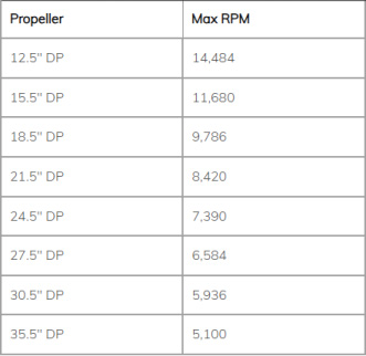
56 . What is the maximum rotational speed of my propeller in revolutions per minute?
A: The tip speed of the propeller must not exceed 0.7 Mach.
57 . Do you have replacement bullet connectors for motor leads?
A: The replacement bullet connector can be obtained here.
58 . Can the wiring of a brushless motor or electronic control unit (ESC) be length-adjusted, or directly welded to other connectors?
A: A standout feature of the system's advanced design is its 200°C heat-resistant copper wires with silicone sheathing, which extend directly from brushless motors and electronic components. This configuration allows users to flexibly adjust wire length, soldering methods, or other modifications according to specific applications. However, please note that certain changes may affect warranty and return policies, so always verify the terms before making any physical alterations. Important reminder: The wires cannot be replaced—make sure to measure twice and cut once, as once modified, the original factory specifications cannot be restored.
59 . Are bullet connectors compatible with brushless motors and electronic speed controllers available?
A: It can be provided.
60 . What is the maximum torque required for adapter installation screws?
A: 12.9mm socket head screw:
M2.5 thread, minimum thread engagement depth 2.5 mm: 1.2 – 1.4 N·m
The minimum thread engagement depth for M3 threads is 3mm: 2.1 – 2.5 N·m
The minimum thread engagement depth of M4 is 4 mm: torque is 4.7–5.8 N·m
When the minimum thread engagement depth of M5 is 5 mm: 9.4 – 11.4 N·m
M6 thread, minimum thread engagement depth 6mm: 16.2 – 19.8 N·m
Applicable to heavy-duty lifting adapter M3 button head screw (Class 10.9): Torque 1.73-2.11 N·m
For the propeller mounting bolts, follow the instructions in the propeller assembly diagram.
 what's app